NUMARK NS7 III
SETUP
Firmware & Drivers
Windows : Install both the Audio and the Display drivers from https://www.numark.com/product/ns7iii
Mac : No drivers are required to be installed for Mac OSX computers
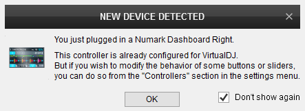
Display Firmware : (for both Windows and Mac) Optionally update the firmware of the LCD screens from https://www.numark.com/product/dashboard (adds some features). Your Numark Displays will be then detected as Dashboard
VirtualDJ 8 Setup
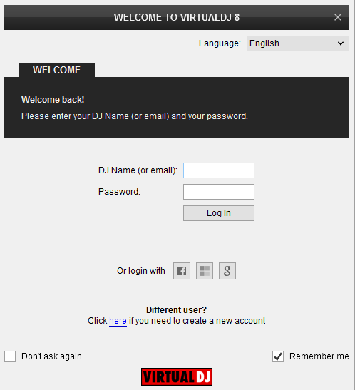
Once VirtualDJ 8 is opened, a Login Window will appear. Login with your virtualdj.com account’s credentials.
A Pro Infinity or a Pro Subscription License is required to use the Numark NS7III. Without any of the above Licenses, the controller will operate for 10 minutes each time you restart VirtualDJ.
http://www.virtualdj.com/buy/index.html
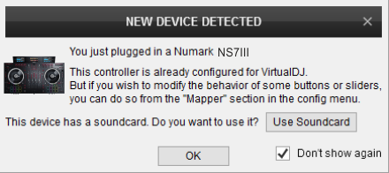
Click on the Use Soundcard button in orderVirtualDJ to apply the pre-defined audio configuration (speakers need to be connected to the rear side of the unit in this case)
Click to OK
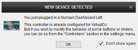
Note that the names may differ depending on the optional firmware update
Click to OK
The unit is now ready to operate.
MIDI Operation
The unit should be visible in the CONTROLLERS tab of Config as 3 devices (Numark NS7III for the main unit and 2 more for the Left and Right LCD Displays) and the “factory default” available/selected from the Mappings drop-down list for all 3 of them.
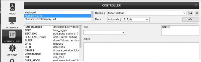
The factory default Mapping offers the functions described in this Manual, however those can be adjusted to your needs via VDJ Script actions.
Find more details at http://www.virtualdj.com/wiki/VDJ8script.html
AUDIO Setup
The unit has a pre-defined Audio setup and a special button in the AUDIO tab of Config to provide that.
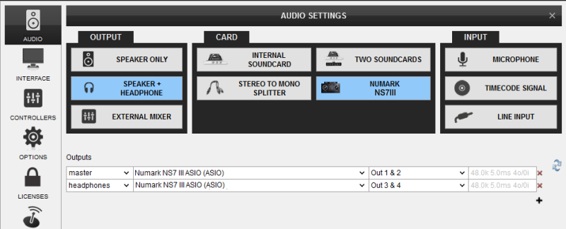
See also Advanced Setup.
For further software settings please refer to the User Guide of VirtualDJ 8.
http://www.virtualdj.com/manuals/virtualdj8/index.html
LAYOUT
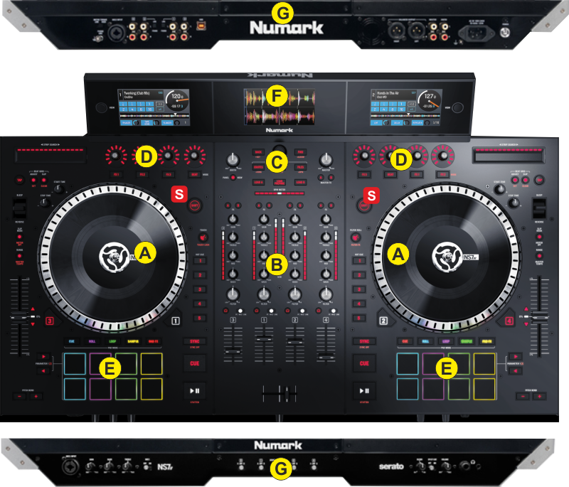
S. SHIFT. Press and hold this button to access secondary functions of other controls on the NS7 III.
The functionality of each button and knob per section (as shown in the image above) will be explained in detail in the next chapters
A. Deck Controls
B. Mixer
C. Browser Controls
D. Effects
E. Pads
F. Displays
G. Front & Rear panels
DECK CONTROLS
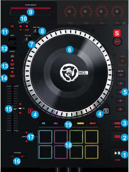
- PLAY. Plays / Pauses the track. Press and hold Shift and then press this button to "stutter-play" the track from the last set Cue Point.
- CUE. When the Deck is paused, you can set a temporary Cue Point by moving the Platter to place the Audio Pointer at the desired location and then pressing the CUE Button.
During playback, you can press the Cue Button to return the track to this Cue Point. (If you did not set a Cue Point, then it will return to the beginning of the track.).
If the Deck is paused, you can press and hold the Cue Button to play the track from the Temporary Cue Point. Releasing the Cue Button will return the track to the temporary Cue Point and pause it. To continue playback without returning to the Temporary Cue Point, press and hold the Cue Button, then press and hold the Play Button, and then release both buttons.
Press and hold SHIFT and then press this button to return to the beginning of the track. - SYNC. Press this button to automatically match the corresponding Deck's tempo with the opposite Deck's (or the Master Deck’s if using a 4 decks Skin) tempo and phase. Press and hold Shift and press this button to set this deck as Master Deck (for 4 decks skins).
- DECK SELECT. Switch Left decks (1 and 3) and Right Decks (2 and 4). The left side of the NS7III will control VirtualDJ decks 1 or 3, and the right side will control VirtualDJ decks 2 or 4.
- HOTCUES. Assigns a Hot Cue Point or returns the track to that Hot Cue Point. When a Hot Cue Button is unlit, you can assign a Hot Cue Point by pressing it at the desired point in your track. Once it is assigned, the Hot Cue Button will light. To return to that Hot Cue Point, simply press it.
Press and hold SHIFT and then press a Hot Cue Button to delete its assigned Hot Cue Point. - JOG. Motorized jogwheel.
- START TIME. Define the time that takes for the track to get its normal speed when Play is pressed.
- STOP TIME. Define the time that takes for the track to completely stop
- STRIP SEARCH. The length of this strip represents the length of the entire track. Place your finger on a point along this sensor to jump to that point in the track (song position).
- BEAT GRID. These buttons offer the ability to manually adjust the CBG of the track. Similar operations are offered at the BPM Editor of VirtualDJ 8.
Hold ADJUST button down and then use the Jogwheel to adjust the width of the CBG Beatgrid (actually the BPM value). The motor will stop (if the track is playing) as long as this button is pressed to assist on precise adjustments.
Hold SHIFT down and then press the ADJUST button to set the First Beat Anchor point, in order the CBG to start moving from that point.
Hold SLIP button down and then use the Jogwheel to adjust the position of the CBG Beatgrid. The motor will stop (if the track is playing) as long as this button is pressed to assist on precise adjustments.
Hold SHIFT down and then press the SLIP button to allow VirtualDJ re-analyze the track and claculate again the BPM and the CBG (will cancel previous adjustments) - BEAT TAP. Manually adjust the tempo of the song. Tap this button at the same tempo as the track to help the software detect a different BPM reading (if needed).
- REVERSE/BLEEP. Reverses audio playback of the track on the corresponding deck. When the switch is in the Reverse position, the playback of the track will be reversed. Returning the switch to its center (deactivated) position will resume normal playback from wherever the Audio Pointer stops.
When the switch is in the Bleep position, the playback of the track will be reversed. Returning the switch to its center (deactivated) position will resume normal playback from where it would have been if you had never engaged the Bleep function (i.e., as if the track had been playing forward the whole time). - SLIP MODE. Press this button to activate the Slip mode. Note that tin the current version of VirtualDJ, the Slip mode only operates with HotCues and Loops. The Slip mode has no effect on the motorized platter.
Press and hold SHIFT and press this button to turn on/off the corresponding Platter's motor. This will not affect the track's playback. - PITCH RANGE/ MASTER TEMPO. Press this button to adjust the range of the Pitch Fader ( to ±6%, ±8%, ±10%, ±12%, ±20%, ±25%, ±33%, ±50%, and ±100%). Press and hold SHIFT and then press this button to "lock" the track's pitch to its original key. The track's tempo will remain at the speed designated by the Pitch Fader
- PITCH. Adjust the track's playback speed (tempo). The white LED next to the fader will light up when the unit’s fader is set at 0%. The Red Up and Down Arrow LEDs will lit if the pitch position of the unit and the actual pitch of the software do not match, to indicate the direction you need to move the hardware fader in order to catch the software one.
- PITCH BEND. Press and hold down to temporary speed up/slow down the song while pressed. When released, the track playback will return to the speed designated by the Pitch Fader
- PADS PARAMETER. Offer different functions depending on the selected PADs Mode. See Pads.
- PADS. Offer various operations, depending on the PADs Mode. See Pads.
- PAD MODES. 9 different PAD Modes are offered. The Leds are colored differently to indicate the Mode. (see Pads)
MIXER
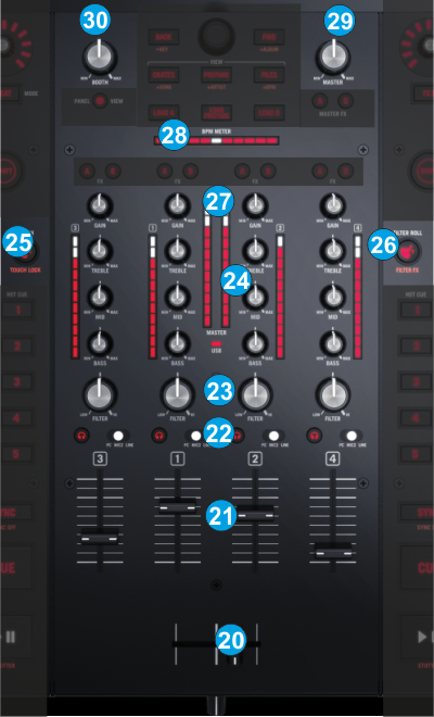
- CROSSFADER. Blends audio between the channels assigned to the left and right side of the crossfader.
- VOLUME. Volume Faders (mixer channel order is 3-1-2-4 decks). Note that the faders will continue to alter the sound of the corresponding software deck, if the PC-MIC2-LINE switchers are on MIC2 or LINE position.
- INPUT SELECTOR. Set this switch to the desired audio source from this channel: PC (a track playing on that layer in the software), Mic 2 or Line (a device connected to the Mic 2 Input or Line Input on NS7III's rear panel). Note: the software deck will still be outputted on Master Output if the switcher is on MIC2 or LINE position.
PFL Press these buttons to send this channel's pre-fader signal to the Cue Channel for monitoring. When engaged, the button will be lit. By pressing one PFL button at a time, you will cue that channel alone (and deactivate PFL monitoring for the other channels). To cue to multiple channels simultaneously, press the PFL buttons for those channels at the same time. - FILTER. Applies a resonance Filter on the software decks. Depending on the FILTER MODE (27) The Filter knob also offers 2 additional functions.
On FILTER ROLL Mode, the knob applies a Loop Roll as well. The size of the loop roll starts from 1/2 beat and ends to 1/16 beat (left or right end position)
On FILTER FX Mode the knob also controls the 1st parameter of the selected effect. On zero position the effect slider gets value 0%, and at the right/left end positions the parameter gets value 100%. - EQ. Adjusts the high (treble) / middle (mid) / low (bass) frequencies. When Touch EQ Mode is activated, touching those knobs will mute the corresponding channel's high/mid/low frequencies (aka "EQ kill").
- TOUCH EQ/FX.
Press this button to enable the FX TOUCH Mode. On this Mode the Touch Capacitors of the FX knobs trigger the Effects while touched.
Press and hold SHIFT and then this button to enable the EQ/FX TOUCH Mode. Led will blink to indicate this mode. On this Mode, the Touch Capacitors of the FX knobs (35) trigger the Effects while touched (same as FX TOUCH Mode), and additionally the EQ Touch Capacitors will kill the corresponding frequencies while touched. - FILTER MODE. Press this button to enable the FILTER ROLL Mode (LED lights on). Holding SHIFT down, the button enables the FILTER FX Mode (LED Flashes). See FILTER (24)
- GAIN. Adjusts the audio level (gain) of the corresponding channel in the software or hardware Input.
- BEATDIFF BAR. This meter is an aid for matching the CBG of both decks. When the white center LED is lit, the CBGs of the left and right selected decks are matched. Otherwise, the meter will tend towards the faster deck. The further from center, the greater the difference between the two BPMs.
- MASTER VOLUME : Adjusts the Master Output Volume (Hardware operation but movement will be visible on the VirtualDJ GUI)
- BOOTH VOLUME. Adjusts the Booth Output Volume (Hardware operation. Movement will not be visible on the VirtualDJ GUI)
BROWSER
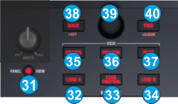
- PANEL VIEW. Press this button to open/close the SideView of VirtualDJ 8 Browser. Hold SHIFT down and then press this button to cycle through the available center mixer panels of the Default VirtualDJ GUI (MIXER, VIDEO, SCRATCH and MASTER)
- LOAD A. Press this button to load the selected track from the Browser to the left assigned deck Hold SHIFT down and then press this button, to unload the left deck.
- LOAD PREPARE. Adds the selected song to the Automix List of Sideview. Hold SHIFT down and then press this button to add the selected song to the Sidelist of Sideview.
- LOAD B. Press this button to load the selected track from the Browser to the right assigned deck Hold SHIFT down and then press this button, to unload the right deck
- CRATES: Sets focus on Folders Window. Press and hold SHIFT and then press to sort the Songs List by Title field.
- PREPARE. Will open the Sideview if closed and will set focus to the Sideview as well. If focus is on the SideView, press this button to cycle though the available views of Sideview (Automix, Sidelist, Sampler, Karaoke and Clone). Hold SHIFT down and then press this button to sort the Songs List by Artist field.
- FILES. Sets focus on Songs List of Browser. Hold SHIFT down and then press this button to sort the Songs List by BPM field.
- BACK. Sets focus to the previous Browser Window. Hold SHIFT down and then press this button to sort the Songs List by Track Number field.
- SCROLL KNOB. Scrolls through Folders or Files. If a track is playing at the Prelisten Player, hold SHIFT down and then use the Scroll knob to navigate through the pre-listened song
SCROLL PUSH. If focus is on the Folders List, expand/collapse Subfolders. Hold SHIFT down and then push the Scroll knob to play/stop the selected track to the Prelisten Player. - FWD. Sets focus to the next Browser Window. Hold SHIFT down and then press this button to sort the Songs List by Album field.
EFFECTS
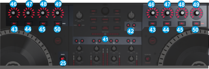
- FX A/B Use these buttons to clone the effects from one deck to the other. E.g. pressing the FXA button on deck 4, it will clone the Effects from Deck 1 to Deck 4 and if SHIFT+FXB is pressed on deck 3, it will clone the Effects from Deck 4 to Deck 3.
- FX MASTER A/B. If FX MASTER A is enabled, the left FX unit (A) will control the Video Transition. If FX MASTER B is enabled, the right FX unit (B) will control the Master Video Effect.
- FX1 button
Single FX Mode. Press this button to trigger the selected Effect. Hold SHIFT down and then press this button to control the Effect button 1 of the selected Effect (if the Effect offers one)
Multi FX Mode. Press this button to trigger the selected Effect on FX Slot 1. Hold SHIFT down and then press this button to select the next Effect for FX Slot 1.
Led will stay lit orange to indicate the Multi FX mode and will blink if the effect slot is activated.
Master FXA/B Mode. If MASTER FXA is selected, the Left FX1 button will trigger the selected Video Transition. If MASTER FXB is selected, the Right FX1 button will trigger the selected Video Effect. - FX2 button
Single FX Mode. Press this button to select the previous Effect from the offered list. Hold SHIFT down and then press this button to control the Effect button 2 of the selected Effect (if the Effect offers one)
Multi FX Mode. Press this button to trigger the selected Effect on FX Slot 2. Hold SHIFT down and then press this button to select the next Effect for FX Slot 2.
Led will stay lit orange to indicate the Multi FX mode and will blink if the effect slot is activated.
Master FXA/B Mode. If MASTER FXA is selected, the Left FX2 button will select the previous available Video Transition. If MASTER FXB is selected, the Right FX2 button will select the previous Video Effect.
. - FX3 button
Single FX Mode. Press this button to select the next Effect from the offered list. Hold SHIFT down and then press this button to control the Effect button 3 of the selected Effect (if the Effect offers one)
Multi FX Mode. Press this button to trigger the selected Effect on FX Slot 3. Hold SHIFT down and then press this button to select the next Effect for FX Slot 3.
Led will stay lit orange to indicate the Multi FX mode and will blink if the effect slot is activated.
Master FXA/B Mode. If MASTER FXA is selected, the Left FX2 button will select the next available Video Transition. If MASTER FXB is selected, the Right FX2 button will select the next Video Effect. - FX1 KNOB.
Single FX Mode. The knob controls the 1st parameter of the selected Effect. Hold SHIFT down and then use this knob to control the 4th parameter of the selected Effect.
Multi-FX Mode: The knobs control the 1st parameter of the selected Effect on FX Slot 1. Hold SHIFT down and then use this knob to control the 2nd parameter of the selected Effect on FX Slot 1.
Master FXA/B Mode. If MASTER FXA is selected, the knob on the left FX unit will control the 1st parameter of the selected Video Transition (if available).
If MASTER FXB is selected, the knob on the right FX unit will control the 1st parameter of the selected Master Video Effect (if available)
When FX Touch Mode (26) is activated, touch the FX 1 Knob to activate its assigned effect, and release the knob to deactivate it - FX2 KNOB.
Single FX Mode. The knob controls the 2nd parameter of the selected Effect. Hold SHIFT down and then use this knob to control the 5th parameter of the selected Effect.
Multi-FX Mode: The knobs control the 1st parameter of the selected Effect on FX Slot 2. Hold SHIFT down and then use this knob to control the 2nd parameter of the selected Effect on FX Slot 2.
Master FXA/B Mode. If MASTER FXA is selected, the knob on the left FX unit will control the 2nd parameter of the selected Video Transition (if available).
If MASTER FXB is selected, the knob on the right FX unit will control the 2nd parameter of the selected Master Video Effect (if available)
When FX Touch Mode (26) is activated, touch the FX 2 Knob to activate its assigned effect, and release the knob to deactivate it - FX3 KNOB.
Single FX Mode. The knob controls the 3rd parameter of the selected Effect. Hold SHIFT down and then use this knob to control the 6th parameter of the selected Effect.
Multi-FX Mode: The knobs control the 1st parameter of the selected Effect on FX Slot 3. Hold SHIFT down and then use this knob to control the 2nd parameter of the selected Effect on FX Slot 3.
Master FXA/B Mode. If MASTER FXA is selected, the knob on the left FX unit will control the 3rd parameter of the selected Video Transition (if available).
If MASTER FXB is selected, the knob on the right FX unit will control the 3rd parameter of the selected Master Video Effect (if available)
When FX Touch Mode (26) is activated, touch the FX 3 Knob to activate its assigned effect, and release the knob to deactivate it - BEAT Encoder. This knob moves forward/backwards the track by 1 beat. While SHIFT is held down, the knob offers 10 times more accuracy (0.1 beat per step).
Push the Encoder to display the FX GUI of the assigned Effect. - BEAT Button. This button offers beat juggle (alternatively jumps one beat forward and backward). Hold SHIFT down and then press this button to toggle between the Single and Multi FX modes (the corresponding panels on the Default 4 Decks GUI of VirtualDJ will follow the selection).
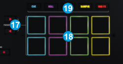
PADS
Pads (18) offer 10 different modes, depending on the PAD MODE SEL buttons (19). Press the same PAD MODE button again to access the additional mode (the LED will blink as an indication).
Each time a mode is selected, a Page will be selected and displayed on the Pads section of the default VirtualDJ skin
Use the PARAMETER < > buttons (17) to adjust the Parameter 1 (if available) of the selected Pads page
Hold SHIFT down and then use the PARAMETER < > buttons (17) to adjust the Parameter 2 (if available) of the selected Pads page
HotCues mode
Press the CUES mode button to set the PADs to HotCue mode (the led of the CUES button will become red). The Hotues page will be then selected and displayed on the Pads section of the VirtualDJ skin
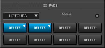
Each one of the 8 pads assigns a Hot Cue Point (1 to 8) or returns the track to that Hot Cue Point.
When a Hot Cue Button is unlit, you can assign a Hot Cue Point by pressing it at the desired point in your track. Once it is assigned, the Hot Cue Button will light up.
Hold SHIFT and then press any of the pads to delete its assigned Hot Cue Point.
Use the PARAMETER < and > buttons to jump to the next or previous HotCue.
Hold SHIFT down and then use the PARAMETER <> buttons to jump the track forward/backwards by 1 beat
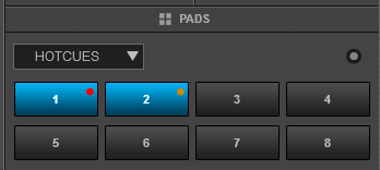
Note: By default Hotcues will get the color of the deck (blue for deck 1, red for deck 2, green for deck 3 and orange for deck 4). A different coloring behavior can be offered via the NonColoredPOI setting (from VirtualDJ Settings OPTIONS tab).
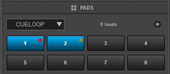
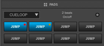
Cue-Loop mode
Press the CUES Mode button twice (or once if the selected mode was HotCues) to set the Pads to HotCue Loop mode (the led of the CUES button will become orange).. The CueLoop page will be then displayed on the Pads section of VirtualDJ skin
Each one of the 8 Pads assigns a Hot Cue Point or returns the track to that Hot Cue Point, but in both cases, it also triggers a momentary or toggle Loop depending on the selected mode.
The currently selected length will be used for the triggered Loop
Hold SHIFT down and then press a pad to jump to the Hot Cue Point but leave the Loop enabled.
Use the PARAMETER < and > buttons to half and double the size of the applied Loop.
Hold SHIFT down and then use the PARAMETER < > buttons to select the On/Off (toggle) or Hold (loop will be enabled while the Pad is pressed) mode
Auto Loop mode
Press the AUTO mode button to set the Pads to Auto Loop mode (the led of the CUES button will become green). The LOOP page will be then selected and displayed in the Pads section of the default VirtualDJ skins.
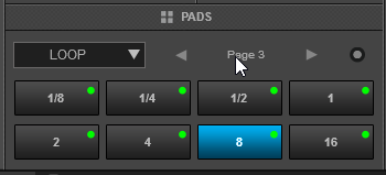
In this mode, each one of the 8 Pads triggers an Auto-Loop of a different size in beats, depending on the selected bank/page from 1/32 to 128 beats
Use the PARAMETER < and > buttons to select a different bank/page with the desired loop sizes.
Hold SHIFT down and then use the PARAMETER buttons to select a trigger mode for the Loops (On/Off, Hold or Roll)
Each time a Loop Size Banks/page is selected, its assigned quick loop values will be displayed on the LCD screen. Due to a firmware limitation, some very small or very large Loop sizes cannot be displayed.
Loop Roll mode
While the Auto Loop mode is selected, press the same AUTO mode button again to set the PADs to Loop Roll mode (the led of the AUTO/ROLL button will become blue). The Loop Roll page will be then selected and displayed in the Pads section of the default skin of VirtualDJ
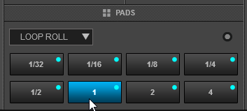
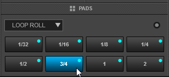
Each one of the 8 Pad triggers a momentary Loop Roll (while pressed) of a different length in beats as per the images above.
In this mode the PARAMETER buttons have no functionality.
The LCD screen displays the sizes of the assigned Loop Rolls for each pad and the size of the triggered Loop Roll as well on the Loop Box.
Manual Loop mode
Press the LOOP mode button to set the Pads to Manual Loop mode (the led of the LOOP button will become green). The Manual Loop page will be then selected and displayed in the Pads section of the VirtualDJ default skin.
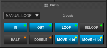
Each one of the 8 pad offers a different loop function.
Use Pads 1 and 2 to set a Loop Entry (In) and a Loop Exit (Out) point for manual looping.
Use Pad 3 to turn off the Loop (if enabled) or trigger a Loop of the selected size in beats
Use Pad 4 to repeat the last triggered loop (reloop)
Use Pads 5 and 6 to half/double the size of the Loop.
Use Pads 7 and 8 to move the Loop (if enabled) forward/backwards by 1 beat
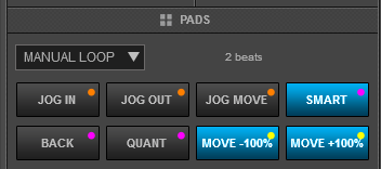
While SHIFT is pressed use ..
Pad 1 to set the Jogwheel to Loop In Adjust mode and use the Jogwheel to fine adjust the Loop In position
Pad 2 to set the Jogwheel to Loop Out Adjust mode and use the Jogwheel to fine adjust the Loop Out position
Pad 3 to set the Jogwheel to Loop Move Adjust mode and use the Jogwheel to fine move the Loop through the track.
Pad 4 to enable/disable Smart Loop. When Smart Loop is enabled (default status), using Loop In and Loop Out buttons to trigger a Manual Loop, will result of a seamless loop (track will stay on beat)
Pad 5 to enable/disable Loop Back mode. When Loop Back mode is enabled, and an Auto Loop is enabled, the current track's position will be considered as the Loop Out (Exit) point of the loop and the passed part of the track will be looped.
Pad 6 to enable/disable Quantize Loop mode. When enabled, the Loop In point of a Loop will be snapped to the nearest beat
Pad 7 and 8 to move the loop (if enabled) forward/backwards by the amount of the size of the loop.
Use the PARAMETER <> buttons to half/double the size of the Loop
Saved Loops mode
Press the LOOP Mode button twice (or once if the selected mode was Manual Loop) to set the Pads to Saved Loops mode (the led of the LOOP button will become pink). The Saved Loops page will be then selected and displayed in the Pads section of the VirtualDJ skins.
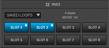
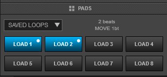
This mode offers the ability to save up to 8 Loops to individual Loop Slots.
Press any Pad to save the current Loop at the current track’s position (of the selected size in beats) to the relative slot. Hold the same Pad down for more than 1 second to delete the Saved Loop.
When a Loop slot is saved, press the corresponding Pad to load (prepare) the Saved Loop.
If the track’s position is before the Saved Loop point, the loop will be enabled but the track will not jump to that position (Prepare status). Use the same Pad to disable the Loop.
Hold SHIFT down and then press one of the lower Pads to load the Saved Loop, but also jump to that position.
Use the PARAMETER < and > buttons to half and double the size of the triggered Loop.
Hold SHIFT down and then use the PARAMETER buttons to move the Loop forward/backwards by 1 beat
Sampler mode
Press the SAMPLER mode button to set the PADs to Sampler mode (the led of the SAMPLER button will become magenta). The Sampler Page will be then selected and displayed in the Pads section of the VirtualDJ default skins
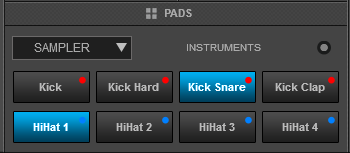
Each one of the 8 pads triggers a sample (1 to 8) from the selected Sampler Bank of VirtualDJ.
The leds of the Pads will automatically get the assigned color of each sample (dark when off, bright when playing).
Press the pads to trigger a sample. Depending on the selected trigger mode, use SHIFT and the same pads to stop the sample.
Use the PARAMETER < and > buttons to select the previous and next Sampler Bank.
Hold SHIFT down and then use the same PARAMETERS buttons to select the previous/next Trigger Pad mode (on/off, hold, stutter, and unmute)
Hold SHIFT down and then press the SAMPLER mode button to start/stop recording the deck to a new Sample (led will blink fast while recording).
Sampler Velocity mode
While the Sampler mode is selected, press the SAMPLER mode button down for at least 2 seconds to set the PADs to SAMPLER Velocity mode. The Led of the SAMPLER mode button will lit purple to indicate the velocity mode. On this mode the Pads trigger the same time, but their Volume will depend on the initial pressure when triggered.
Hold SHIFT down and then press the SAMPLER mode button down for at least 2 seconds to set the PADs to SAMPLER After Touch Velocity mode. The Led of the SAMPLER mode button will lit blue to indicate the velocity mode. On this mode the Pads trigger the same time, but their Volume will depend on the continuous pressure.
Tip: To return all samples to their maximum values after the Velocity mode is used, select the next or previous available bank and then select the current again.
Slicer mode
Press the SLICER mode button to set the PADs to Slicer mode (the led of the SLICER button will become cyan).The Slicer Page will be then selected and displayed in the Pads section of VirtualDJ skin.
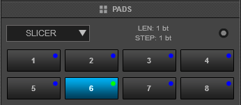
The eight pads represent eight sequential beats/Slices in the Beat Grid. The playing Slice is represented by the currently green lit pad. The green light will "move through the pads" as it progresses through each eight-Slice phrase. Press a pad to repeat that Slice (hold it down if you want to keep looping it). Once the Pad is released the track will continue to play from the position it would have been if the pad was never pressed.
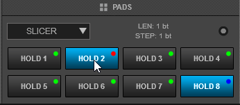
Hold SHIFT button down and then use the same Pads to use the Slicer in Hold mode. In this mode, the slices are memorized (using the last triggered ones)
Use the PARAMETER < and > buttons to adjust the length of the Loop applied to the slice. Press SHIFT and then use the same PARAMETERS < and > buttons to adjust the step of the Slices.
Beatjump mode
While the Slicer mode is selected, press the same SLICER mode button again to set the PADs to Beat Jump mode. The BeatJump page will be then selected and displayed on the Pads section of the VirtualDJ skin
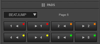
In this mode, each one of the Pads will jump the track backwards/forward by the amount of beats depending on the selected page/bank (from 1/8 beats to 32 bars)
Use the PARAMETER < > buttons to select a different bank/page with the desired size of beat jumps
Front & REAR Panels

- MIC 1 INPUT. Connect a 1/4" microphone to this input. This input's audio signal is routed directly to the Program Mix and Cue Mix.
- MIC GAIN/EQ. Adjust the gain, the low (bass) frequencies and the high (treble) frequencies of the microphone channel.
- MIC ON/OFF. When set to ON, the Mic 1 Input is active, and its audio signal is routed directly to the Program Mix and Cue Mix. When set to OFF, the Mic 1 Input is disabled.
- XFADER ASSIGN LEFT: Routes the audio playing on the corresponding channel 1 or 3 to either side of the crossfader (A or B), or bypasses the crossfader and sends the audio directly to the Program Mix (center, THRU).
- XFADER CURVE. Adjusts the slope of the crossfader curve. Turn the knob to the left for a smooth fade (mixing) or to the right for a sharp cut (scratching). The center position is a typical setting for club performances.
- XFADER ASSIGN RIGHT: Routes the audio playing on the corresponding channel 2 or 4 to either side of the crossfader (A or B), or bypasses the crossfader and sends the audio directly to the Program Mix (center, THRU).
- HEADPHONES BLEND: Turn to mix between Cue and Program in the Headphone channel. When all the way to the left, only channels routed to Cue will be heard. When all the way to the right, only the Program mix will be heard.
- HEADPHONES SPLIT. When this switch is in the ON position, the headphone audio will be "split" such that all channels sent to Cue are mixed to mono and applied to the left headphone channel and the Program mix is mixed to mono and applied to the right channel. When the switch is in the OFF position, Cue and Program audio will be "blended" together.
- HEADPHONES VOLUME. Adjusts the volume level of the headphone output.
- HEADPHONES SOCKET. Connect your 1/4" or 1/8" headphones to this output for cueing and mix monitoring.
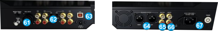
- MIC 2 INPUT. Connect a 1/4" microphone to this input. Microphone controls are located on the top panel on any channel whose Input Selector is set to Mic2
- LINE INPUTS. Connect your audio sources to these inputs. Inputs 1 and 2 can accept both line and phono-level signals.
- USB. This USB connection sends and receives audio and control information from a connected computer.
- MASTER OUTPUT (XLR): Connect this low-impedance XLR output to a PA system or powered monitors. The level of this output is controlled with the Master knob on the top panel.
- MASTER OUTPUT (RCA): Use standard RCA cables to connect this output to a speaker or amplifier system. The level of this output is controlled by the Master knob on the top panel.
- BOOTH OUTPUT (RCA): Use standard RCA cables to connect this output to a booth monitoring system. The level of this output is controlled by the Booth knob on the top panel.
- POWER: Use the included power cable to connect NS7III to a power outlet. While the power is switched off, plug the cable into NS7III first, and then plug the cable into a power outlet. Use the Power Switch to turn the NS7III on and off. Turn on NS7III after all input devices have been connected and before you turn on amplifiers. Turn off amplifiers before you turn off NS7III.
Advanced Audio Setup
Inputs
The Numark NS7III offers the ability to use the unit as a stand-alone mixer.
Assign a Mixer Channel as external Source and route an Analogue Source (CD player, turntable etc) to the Master Output of the unit. Simply connect your analogue source to the rear side (Inputs) and set the PC/MIC/LINE Switcher of a mixer Channel to LINE.
Note that if a Switcher is set to either MIC or LINE, the Mixer Channel will still control the Mixer Channel of VirtualDJ, therefore the corresponding software deck should not be used (played) as both signals will be routed to the Master Output.
Timecodes
The Numark NS7III offers the ability to use its inputs as Timecode (DVS) control
To-Do.
Recording
The pre-defined Audio configuration of VirtualDJ 8 for the Numark NS7II provides the ability to record your mix without any further adjustments.
However, if you wish to record both the software mix and the Inputs (Microphone and Line Ins) at the same time, you will need to add a Record Line to the Audio Setup as per the following image.